Industrial Heat Recovery Plans: Engineering & Thermodynamic Architecture
The modern heavy manufacturing sector operates within an increasingly narrow corridor of energetic and fiscal efficiency. For over a century, industrial processes were designed under an assumption of resource abundance, where primary thermal energy was used once and immediately exhausted to the atmosphere through cooling towers, stacks, and effluent streams. Industrial Heat Recovery Plans. This linear thermodynamic model is no longer defensible. As global regulatory frameworks tighten and energy price volatility compounds, the extraction of latent value from waste thermal streams has transformed from an idealistic sustainability initiative into a core requirement for operational survival.
Developing a high-performance framework for thermal recycling requires navigating the complex laws of thermodynamics rather than simple mechanical component selection. A poorly specified system can easily introduce severe backpressure into an upstream smelting furnace, alter the dew point of a flue gas stack to cause localized acid condensation, or experience rapid mechanical delamination due to thermal stress.
To construct a durable, long-term capital strategy, plant engineers and operations directors must look beyond basic heat capture hardware. The modern vanguard of industrial energy management relies on system-wide thermal integration and precise thermodynamic grade mapping. This article provides an exhaustive engineering reference for analyzing, designing, and executing deep-tissue heat recovery frameworks within complex process environments, establishing a definitive benchmark for systemic resilience and operational optimization.
Understanding “industrial heat recovery plans”
At an institutional and industrial scale, the generation of industrial heat recovery plans represents a radical departure from localized, piece-meal energy auditing. The most critical error made by project stakeholders is treating thermal recycling as an isolated mechanical add-on rather than an integrated, plant-wide process modification.
A sophisticated analysis must begin by distinguishing between thermal quantity and thermal quality. A massive volume of low-temperature wastewater may contain more total energy (BTUs) than a small stream of high-temperature exhaust gas, yet its low thermodynamic grade limits its practical utility. True mastery in composing industrial heat recovery plans requires a deep understanding of exergy—the maximum useful work obtainable from a thermal stream. Plans that fail to account for exergy profiles frequently result in the installation of oversized, underperforming heat exchangers that never achieve their engineered payback targets.
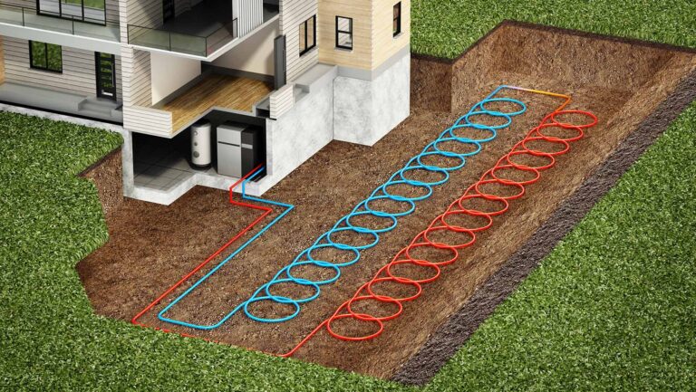
Furthermore, these blueprints must bridge the physical distances within an industrial footprint. In large-scale chemical or petrochemical facilities, the source of waste heat is rarely adjacent to the potential thermal sink. Advanced integration roadmaps insulate against this reality by designing high-efficiency thermal loops, phase-change distribution media, or organic Rankine cycle (ORC) power generation arrays that convert low-grade heat directly into plant-grid electricity. It is this multi-layered harmonization of fluid dynamics, metallurgical constraints, and variable manufacturing schedules that differentiates a resilient thermal asset from an expensive, maintenance-intensive engineering liability.
Historical Context and Thermodynamic Evolution
The historic trajectory of heavy manufacturing has track-stepped with the evolution of combustion technology and steam cycle design.
[Early Linear System]    ---> Single-use fuel fuel combustion ---> 60% Exhust Loss ---> Zero Sequestration
[Mid-Century Recovery]   ---> Basic localized economizers    ---> High fouling rate ---> Susceptible to acid dew point
[Modern Regenerative]    ---> Systemic Pinch Integration      ---> Variable Grade ORC ---> Active grid power co-generation
The dawn of the 21st century brought a profound shift driven by the professionalization of building science and process engineering. The industry transitioned from localized thermal capture to system-wide network integration, pioneered by the development of Pinch Analysis.
Conceptual Frameworks: The Physics of Thermal Grade Analysis
To engineer an authoritative waste heat recovery network, facilities directors rely on specific thermodynamic and building science models:
-
The Pinch Technology Model: A systematic methodology for mapping all hot and cold streams within a manufacturing facility onto a single composite temperature-enthalpy graph. This identifies the “pinch point”—the absolute thermodynamic limit past which no heat should be transferred between streams of inappropriate temperatures, optimizing the sizing of the entire heat exchanger network.
-
The Exergy Destructive Framework: A mental model that quantifies the irrecoverable loss of useful work when a high-temperature waste stream is inappropriately matched with a low-temperature sink.
-
The Acid Dew Point Avoidance Protocol: A chemical engineering calculation that determines the absolute minimum temperature to which a sulfur-bearing flue gas stream can be cooled before sulfuric acid begins to condense out of the gas phase onto cold metal surfaces, triggering catastrophic structural corrosion.
-
The Logarithmic Mean Temperature Difference (LMTD) Matrix: A mathematical tool used to determine the true temperature driving force within heat transfer equipment, dictating whether a co-current, counter-current, or cross-flow heat exchanger geometry will yield the maximum thermal exchange per square meter of alloy surface.
Typologies, Heat Exchanger Classifications, and Media Trade-offs
Industrial heat recovery systems vary fundamentally by material composition, flow geometry, and phase interaction. A failure to align the specific heat exchanger morphology with the chemical and physical characteristics of the fluid stream is a leading cause of premature mechanical failure.
| Equipment Typology | Heat Transfer Mechanism | Thermal Grade Compatibility | Primary Operational Liability |
| Shell and Tube Exchanger | Indirect conductive fluid-to-fluid | High to Ultra-High (up to 1600°F) | Massive physical footprint, prone to high-pressure tube delamination |
| Plate and Frame Exchanger | High-surface corrugated gasketed plates | Low to Medium (up to 350°F) | Highly sensitive to particulate fouling and seal degradation |
| Regenerative Thermal Wheel | Rotating porous matrix mass transfer | Low to Medium (up to 500°F) | Cross-contamination risk between intake and exhaust streams |
| Heat Pipe Array | Sealed phase-change capillary tubes | Medium (200°F to 800°F) | Limited maximum heat flux per individual tube element |
| Run-Around Coil Loop | Distant coupled hydronic pumping | Low (50°F to 150°F) | Parasitic electrical load from continuous fluid circulation pumping |
Decision Logic for System Engineering
The physical state and chemical corrosivity of the waste stream must dictate the underlying structural logic. If a glass manufacturing facility emits ultra-high-temperature exhaust (1200°F) laced with abrasive particulates, the engineering logic requires heavy-gauge alloy radiative recuperators or ceramic shell-and-tube configurations. If a pharmaceutical batch facility discharges clean, low-temperature water (140°F), the logic shifts toward highly compact, corrugated marine-grade stainless steel plate-and-frame exchangers configured for rapid disassembly and sanitization.
Detailed Real-World Scenarios and Operational Failure Modalities Industrial Heat Recovery Plans
Scenario 1: Flue Gas Delamination via Sulfur Condensation
An industrial cement manufacturing facility executed an un-modeled energy retrofitting initiative, installing a high-density finned economizer inside its primary kiln flue gas stack to preheat boiler feedwater. On paper, the system project goals showed an immediate eight percent reduction in natural gas consumption. However, within nine months, the lower section of the economizer suffered catastrophic structural delamination, leaking pressurized water into the main exhaust stream and forcing an immediate facility-wide shutdown.
The engineering team failed because the industrial heat recovery plans omitted a dynamic chemical dew-point simulation. The kiln exhaust contained variable concentrations of sulfur dioxide. By cooling the flue gas from 450°F down to 210°F to maximize heat capture, the metal surface temperature dropped below the acid dew point (240°F). Sulfuric acid vapor condensed directly onto the steel fins, triggering rapid, localized pitting corrosion.
Remediation required replacing the economizer with a specialized glass-coated tube array and integrating a automated bypass valve loop that maintains the stack exhaust above 260°F during low-load manufacturing cycles.
Scenario 2: Severe Parasitic Load Pumping Imbalances
A high-volume chemical processing plant implemented a run-around coil loop to transfer waste heat from an exothermic reaction vessel over a distance of four hundred feet to a raw material pre-heating tank. The system utilized a standard water-glycol mixture as the heat transfer medium. Due to a failure to calculate the dynamic viscosity changes of the glycol during winter temperature dips, the circulating pumps experienced massive hydraulic drag.
The second-order effect was profound: the electrical energy consumed by the high-horsepower circulating pumps exceeded the thermal BTU value captured from the reaction vessel. The system transformed from an energy recovery asset into a net-negative operational drain. The integration framework should have specified variable-frequency drive (VFD) pumping systems modulated by real-time differential temperature telemetry, allowing the system to idle when the thermal gradient dropped below a critical threshold.
Economic Architecture: Capital Dynamics and Variable Horizons
The capital profiling of an industrial thermal overhaul cannot be assessed using simplistic, mass-market payback periods. Enterprise accounting must shift toward Levelized Cost of Saved Energy (LCOSE) and Net Present Value (NPV) evaluations that extend across the fifteen- to twenty-five-year operational lifecycle of heavy machinery.
| Capital Factor | Standard Procurement | High-Performance Engineering | 25-Year Strategic Impact |
| Upfront Alloy Procurement | Carbon steel commodity lines | Titanium or Hastelloy superalloys | Low initial cost, but guarantees severe replacement overhead within 5 years |
| Pinch Optimization Software | Ignored / Linear assumption | Multi-stream continuous modeling | Maximizes cross-process integration, reducing total heat exchanger area |
| Parasitic Pumping Allocation | Fixed-speed induction pumps | Variable-frequency smart pumps | Eliminates energy-neutral or net-negative operational windows |
| Regulatory Carbon Offsets | Uncalculated | Monetized Scope 1 reductions | Generates continuous cash flows under tightening environmental tax laws |
The opportunity cost of failing to implement comprehensive thermal blueprints includes not only immediate fuel waste, but also the risk of structural regulatory non-compliance as state and federal mandates begin enforcing hard EUI (Energy Use Intensity) caps on heavy industrial zones.
Advanced Tools and Strategic Engineering Systems Stack
Executing definitive thermal integration demands an enterprise software and hardware stack operating at the vanguard of modern mechanical engineering:
-
Aspen Energy Analyzer: The industry-standard software tool used to perform continuous pinch analysis, optimize heat exchanger networks, and simulate the thermodynamic impacts of process changes before physical construction.
-
Computational Fluid Dynamics (CFD): High-resolution modeling of exhaust stacks and fluid junctions to eliminate localized turbulence zones that accelerate erosion-corrosion phenomena.
-
Organic Rankine Cycle (ORC) Turbines: Solid-state power generation modules that utilize high-molecular-weight working fluids to generate electricity from thermal streams as low as 180°F.
-
Ultrasonic Flow Telemetry: Non-invasive clamp-on sensors that measure real-time mass flow rates within high-temperature piping without introducing pressure drops or leaking hazards.
-
Variable-Geometry Thermostatically Controlled Valves: Specialized valves that dynamically re-route fluid streams based on real-time temperature fluctuations, ensuring that heat exchangers never experience extreme thermal shock during emergency process shutdowns.
-
Acoustic Soot Blowers: Systems that deploy low-frequency sonic waves inside exhaust economizers to continuously break up particulate accumulation on heat transfer surfaces without requiring physical shut-downs for manual cleaning.
Risk Taxonomy and Compounding Systemic Failures
Industrial heat recovery networks are highly coupled systems; an un-modeled intervention in an exhaust stream can trigger cascading mechanical failures across distant production zones.
[Improper Economizer Sizing] ---> [Increased Flue Backpressure] ---> [Altered Kiln Draft Dynamics] ---> [Incomplete Product Combustion]
-
Hydraulic Resonance Amplification: When plate-and-frame exchangers are subjected to high-velocity pulsating flows from positive-displacement pumps, they can enter a harmonic resonance state. This vibration rapidly wear down interior gaskets, triggering massive cross-contamination between toxic process fluids and clean utility water loops.
-
The Thermal Shock Cascade: Rapidly introducing a cold fluid stream into a hot, un-preheated shell-and-tube exchanger can cause immediate metallurgical distortion, resulting in tube-sheet cracking and high-pressure fluid flashing.
-
The Fouling-Induced Backpressure Trap: Particulate accumulation on the exterior of finned tubes restricts the physical cross-sectional area of an exhaust stack. This restriction increases backpressure on upstream combustion blowers, driving down fuel efficiency and potentially triggering flame-out safety shutdowns on primary boilers.
Governance, Asset Longevity, and Lifecycle Maintenance
An authoritative thermal infrastructure asset requires a continuous, data-driven governance framework to prevent performance drift and preserve the internal rate of return.
-
Systemic Re-Commissioning Protocols: Industrial processes evolve; modifications to a product recipe alter the temperature and mass flow profiles of the waste streams. Every 36 months, the facility’s master pinch model must be audited and re-calibrated against current operational baselines.
-
Non-Destructive Tube Testing: High-temperature recuperators are subject to continuous internal wear. A definitive maintenance strategy deploys eddy-current or ultrasonic testing during scheduled plant turnarounds to map tube wall thinning before a catastrophic breach occurs.
-
Layered Maintenance Checklist:
-
Shift-Level: Monitor differential pressure ($\Delta P$) across all gas-to-liquid exchangers to detect early particulate fouling.
-
Monthly: Analyze chemical composition of heat-transfer fluids to identify early thermal cracking or fluid oxidation.
-
Annually: Conduct full thermographic scans of all external structural insulation jackets to locate hidden thermal bypasses or refractory breakdown zones.
-
Measurement, Tracking, and Systemic Validation Metrics
Validating the execution of industrial heat recovery plans requires separating raw energy capture metrics from genuine plant-wide efficiency improvements:
-
Leading Indicators: Real-time exergy efficiency calculations, continuous heat exchanger cleanliness factors ($U/U_{clean}$ trends), and power-to-pumping parasitic ratios.
-
Lagging Indicators: Verified reductions in facility-wide MMcf natural gas consumption adjusted for manufacturing volume metrics, and measurable drops in total cooling tower heat rejection loading.
-
Documentation Architecture: Maintain a permanent, immutable engineering master file containing complete point-by-point process single-line diagrams (P&IDs), baseline metallurgical certification sheets, fluid dynamic pressure logs, and time-stamped pre-retrofit thermal baselines captured across all operational seasons.
Deconstruction of Common Industry Misconceptions
-
Myth: “Any source of waste heat can be efficiently converted into electricity.”
Reality: Power generation via systems like ORC requires a clear, consistent temperature delta. Attempting to generate electricity from vast streams of ultra-low grade heat (under 130°F) yields exceptionally low thermal efficiencies, often making direct thermal utilization (such as space preheating) far more economically viable.
-
Myth: “Installing a heat exchanger always improves a facility’s total efficiency.”
Reality: If a heat exchanger introduces high fluid friction or pressure drops, the additional electrical energy demanded by upstream fans and pumps can entirely negate the captured thermal value, resulting in a net increase in plant operating costs.
-
Myth: “Fouling is a minor maintenance issue that can be solved by oversized design.”
Reality: Simply oversizing a heat exchanger to compensate for expected fouling reduces fluid velocities within the tubes. This lower velocity accelerates the deposition of solids, worsening the fouling problem and decreasing the equipment’s lifecycle.
-
Myth: “Thermal integration makes a manufacturing plant rigid and difficult to operate.”
Reality: While highly integrated networks require precise control, the incorporation of automated bypass lines and variable-geometry distribution valves allows modern heat recovery systems to dynamically adapt to shifting production schedules without interrupting core manufacturing processes.
Ethical and Contextual Considerations in Thermal Infrastructure
The implementation of heavy industrial energy management systems carries broader social and environmental implications that go beyond internal corporate profit margins. When a manufacturing facility fails to optimize its thermal profile, it dumps massive quantities of low-grade heat directly into adjacent waterways or urban airsheds. This thermal pollution can significantly alter local microclimates, accelerate harmful algal blooms in nearby rivers, and exacerbate the urban heat island effect in surrounding communities.
Conversely, a properly executed thermal blueprint can serve as a vital community asset. Across the United States, forward-thinking industrial facilities are entering into public-private partnerships to route their clean, low-grade waste heat into district heating networks for municipal buildings, agricultural greenhouses, or low-income residential districts. This transformation elevates the manufacturing plant from an isolated environmental burden to an integrated anchor of community resilience.
Furthermore, engineering teams must maintain absolute transparency regarding the material sourcing and lifecycle carbon impact of the recovery equipment itself. Specifying exotic nickel-based superalloys or heavy titanium plate components involves deep supply chain extraction costs.
Conclusion
The structural execution of industrial heat recovery plans is a core discipline within modern chemical and mechanical process engineering. As the global manufacturing landscape faces unprecedented resource constraints and regulatory pressures, the line between viable enterprises and obsolete facilities will be drawn by the efficiency of their thermal architectures. Treating waste heat not as an unavoidable byproduct, but as a valuable, stratified asset ensures that an industrial facility can defend its margins and drastically minimize its environmental footprint.