Top Geothermal Heating Plans: A Definitive Guide to Subsurface Thermal Infrastructure
The decarbonization of the built environment requires a structural shift in how thermal energy is generated, stored, and distributed. For decades, space heating and domestic hot water production have relied on the combustion of fossil fuels or the inefficiencies of high-load electric resistance systems. Top Geothermal Heating Plans. As municipal electrification mandates tighten, grid capacities face systemic constraints, and utility costs fluctuate, the extraction of low-grade shallow geothermal energy has transitioned from a niche environmental alternative to a core infrastructure strategy.
Deploying ground-source heat pump (GSHP) systems at scale requires moving beyond a simple equipment-replacement mindset. The ground beneath a structure or district functions not merely as an infinite heat sink or source, but as a dynamic thermal battery. The design, capitalization, and execution of subsurface thermal assets demand meticulous thermodynamic engineering, hydrogeological risk management, and long-term financial modeling. Without this granular preparation, high-performance thermal infrastructure can quickly deteriorate into an operational liability.
An authoritative assessment of these systems requires deconstructing the physical, geological, and regulatory layers that govern modern geo-exchange networks. Whether an asset manager, structural engineer, or institutional developer is evaluating a localized vertical borehole network, a sprawling horizontal closed-loop configuration, or an open-loop aquifer thermal energy storage system, the value proposition remains identical: structural permanence paired with long-term cost predictability. This analysis deconstructs these operational layers, establishing an analytical blueprint to evaluate, execute, and govern subsurface thermal designs across a multi-decade operational horizon.
Understanding top geothermal heating plans
To accurately evaluate top geothermal heating plans, one must look past standard HVAC product specifications and focus on the systemic integration of the building’s thermal envelope with localized geology. The term does not describe a generic equipment package or a basic service contract. Instead, it refers to a complex, site-specific blueprint that coordinates subsurface loop mechanics, fluid dynamics, coefficient of performance (COP) tracking, and regulatory environmental constraints.
A common structural misunderstanding in this sector is treating a ground-source heat pump as a standalone product comparable to an air-source equivalent. Air-source systems interact with an unconstrained, turbulent atmospheric boundary layer. Geothermal assets operate within a closed, conductive, and convective lithospheric matrix. True top-tier plans bridge this gap by starting with an independent, in-situ Thermal Conductivity Test (TCT). This rigorous field evaluation measures the actual rate of heat transfer through local rock strata, ensuring the physical loop design matches the specific thermodynamic limits of the site rather than relying on generic regional estimates.
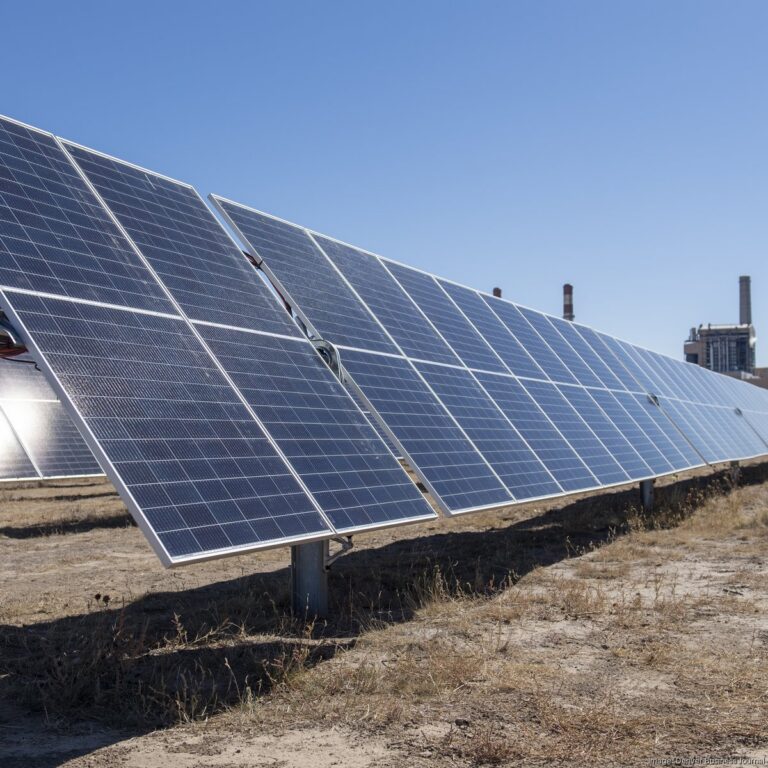
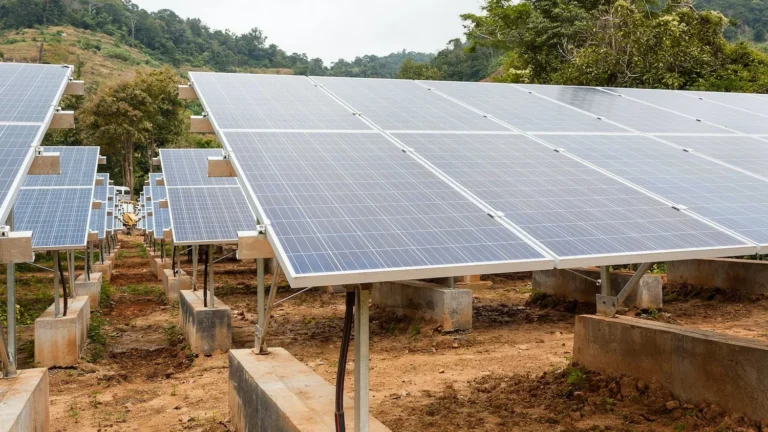
Oversimplification risks in this domain frequently manifest as a failure to balance the annual thermal load profile of the building. If a structure located in a cold climate requires massive heat extraction during the winter but offers minimal heat rejection back into the ground during the summer, the surrounding soil temperature will drop steadily year after year. Over a ten-year horizon, this unmitigated extraction creates a localized permafrost zone around the boreholes, causing the heat pump’s COP to plummet and eventually leading to systemic mechanical failure. The most sophisticated modern frameworks utilize hybrid thermal balancing. This approach integrates supplemental solar thermal arrays, dry coolers, or industrial waste heat capture to actively maintain the long-term equilibrium of the ground battery, fundamentally redefining what constitutes an effective, high-utility plan.
Historical Paradigm Shifts and Systemic Evolution
The engineering principles behind geo-exchange technology have progressed through three distinct phases, each defined by advancements in materials science, drilling mechanics, and thermodynamic modeling software.
The Experimental and Direct-Use Era (Early 20th Century to 1970s)
Early geothermal applications relied primarily on high-temperature hydro-geothermal anomalies—hot springs and deep volcanic aquifers—for direct district space heating. These early open-loop systems were limited to specific geographic fault lines, such as those in Iceland or parts of the Western United States. The mechanical components were rudimentary, often suffering from severe mineral scaling, corrosion, and downhole pump degradation due to the chemical volatility of unmanaged thermal fluids.
The Commercialization and Polyethylene Era (1980s to 2010s)
The widespread adoption of High-Density Polyethylene (HDPE) and Cross-linked Polyethylene (PEX) revolutionized the industry, providing developers with chemically inert, incredibly durable materials capable of handling continuous heat transfer without structural degradation. Closed-loop configurations became the industry standard, insulating the primary circulating heat transfer fluid from the surrounding groundwater matrix. During this phase, engineering models were refined from crude rule-of-thumb calculations to standardized design protocols, such as those established by the International Ground Source Heat Pump Association (IGSHPA).
The Networked District and Thermal Microgrid Era (2020s to Present)
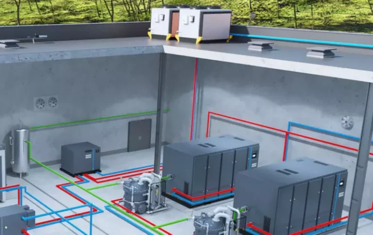
The modern landscape is defined by the transition from individual, building-isolated loops to interconnected Ambient Loops and Thermal Microgrids. These shared-infrastructure networks link multiple diverse building types—commercial offices, multi-family residential units, and industrial facilities—into a single closed hydraulic loop. This configuration allows for real-time thermal balancing across different load profiles; the waste heat rejected by a data center’s cooling cycle is instantly captured and used to heat a nearby apartment complex’s domestic water supply.
Conceptual Frameworks and Subsurface Mental Models
To effectively analyze and design an institutional geo-exchange project, engineering teams rely on several fundamental mental models:
-
The Thermal Battery Analogy: This model dictates that the ground heat exchanger is not an infinite supply of energy, but a storage vessel with strict volumetric limits. Every unit of thermal energy extracted during the heating season must be systematically accounted for, and ideally replenished, through cooling-season heat rejection or passive solar charging to prevent long-term capacity degradation.
-
The Reynolds Number Threshold: This fluid dynamics framework governs the flow velocity of the heat transfer fluid within the underground loop. The system must maintain a high enough Reynolds number to ensure turbulent flow, which maximizes the rate of heat transfer through the pipe wall into the surrounding grout and rock, while balancing the increased pumping power required to overcome fluid friction.
-
The Grout-to-Strata Thermal Bridge: This model evaluates the efficiency of the solid interface between the loop pipe and the borehole wall. The selection of thermal grouts mixed with specific silica sand ratios represents a critical optimization path; any void or low-conductivity zone within the borehole directly introduces thermal resistance, forcing the entire system to run longer hours and reducing overall operational efficiency.
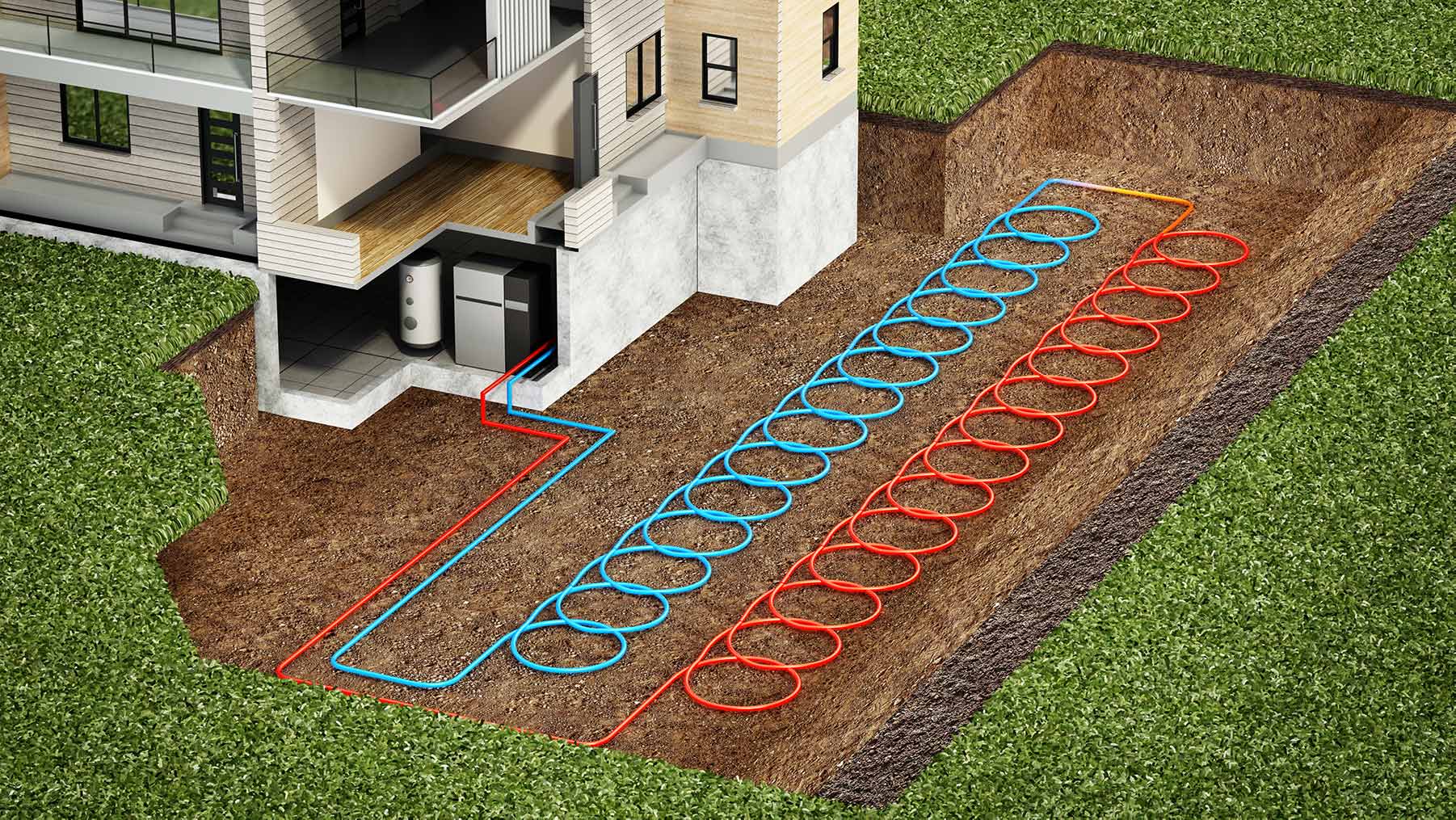
Loop Classifications, Geometries, and Engineering Trade-offs
Modern subsurface thermal infrastructure can be deployed across several distinct geometries, each presenting clear compromises across capital requirements, land utilization, hydrogeological risk, and raw thermodynamic output.
| Loop Geometry | Surface Footprint Required | Average Capital Expenditures | Primary Failure Mode | Regulatory/Environmental Hurdles |
| Vertical Closed-Loop Boreholes | Low (Concentrated array) | High (Drilling costs per foot) | Borehole grout settling/voids | Medium (Aquifer protection zoning) |
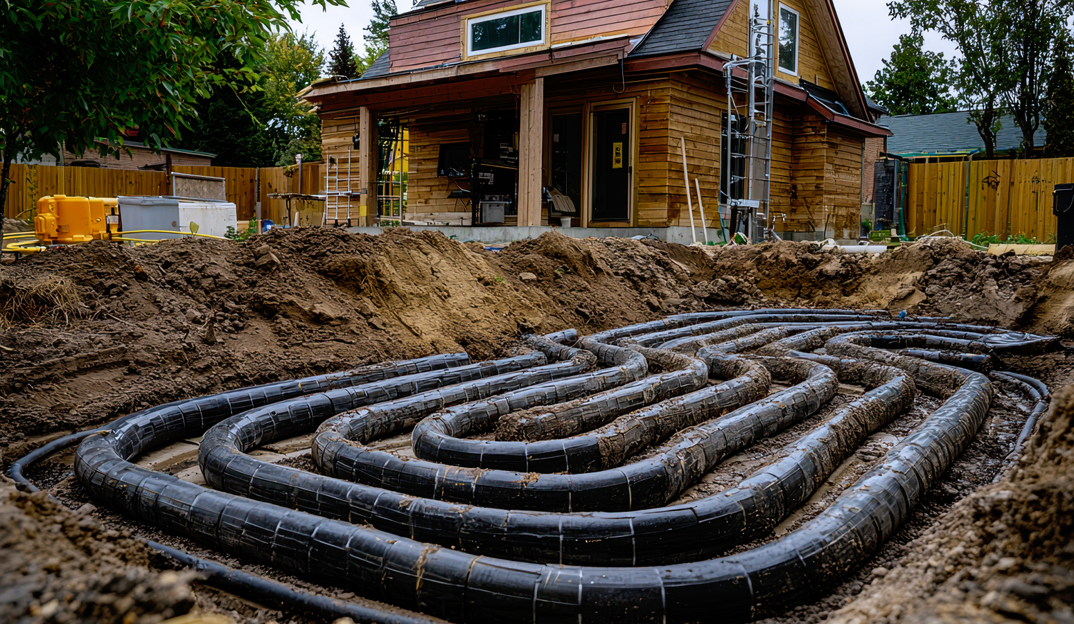
| Horizontal Slinky/Trench Loops | High (Extensive acreage) | Low (Standard excavation) | Soil dry-out / Loss of thermal contact | Low (Shallow disturbance only) |
| Open-Loop Aquifer Pumping (ATES) | Low (Two or more active wells) | Medium (Lower drilling volume) | Well screening mineralization / Clogging | High (Groundwater extraction permits) |
| Surface Water Closed-Loop (Pond/Lake) | Variable (Requires adjacent water body) | Low (No drilling/excavation) | Marine biofouling / Anchor damage | High (Riparian ecosystem regulations) |
| Energy Piles / Structural Foundations | Zero (Integrated into structural pillars) | Medium (Incremental construction cost) | Concrete thermal expansion cracking | Low (Integrated with standard building permit) |
The decision logic governing these configurations depends heavily on site constraints and building type. A urban high-rise development with a minimal surface footprint cannot execute horizontal trenching or surface water loops due to absolute land scarcity. Conversely, a suburban corporate campus or large rural institutional facility with ample acreage can leverage horizontal configurations or slinky arrays.
Deep Operational Scenarios and Real-World Thermal Stress Tests Top Geothermal Heating Plans
Evaluating the true performance of a subsurface thermal design requires analyzing how these configurations react under severe hydrogeological and structural stress.
Scenario A: The Long-Term Borehole Thermal Drift
An institutional educational campus in the Upper Midwest deploys a large 100-borehole vertical array designed around a top geothermal heating plans framework to manage its space heating load. The design assumes a perfectly balanced winter extraction and summer rejection profile.
-
The Subsurface Constraint: The surrounding granite strata possesses low groundwater movement, limiting convective heat restoration.
-
The Operational Impact: The baseline ground temperature drops from 52°F to 39°F over seven years, causing the heat pumps’ operational heating COP to degrade from 4.2 to 2.6.
-
The Intervention Protocol: The engineering team must install a supplemental rooftop dry cooler array to intentionally inject heat into the borehole field during peak summer days, restoring the ground battery’s thermal equilibrium and stabilizing future winter operational costs.
Scenario B: Open-Loop Aquifer Mineralization and Iron-Oxide Clogging
A commercial high-rise in the Pacific Northwest utilizes a high-volume open-loop aquifer thermal energy storage (ATES) plan, pumping water from a deep gravel aquifer, passing it through an internal plate heat exchanger, and reinjecting it into a secondary down-gradient well.
-
The Hydrogeological Reality: The local groundwater contains high concentrations of dissolved iron and manganese.
-
The Failure Mode: Atmospheric oxygen enters the injection well casing during maintenance cycles, causing the dissolved iron to oxidize and precipitate out of solution as solid iron oxide. This solid precipitation clogs the gravel pack surrounding the injection well screen within 18 months.
-
The Resulting Impact: Injection well pressure rises rapidly, forcing downhole pumps to consume excessive energy and triggering high-pressure safety shutdowns that cut off the building’s thermal regulation entirely.
-
The Correction Strategy: The system must implement a strict closed-nitrogen blanket system within the well casings to eliminate oxygen exposure, paired with a biannual chemical acidification program using sulfamic acid to dissolve iron scale and maintain well injectivity.
Scenario C: Horizontal Slinky Degradation via Severe Structural Soil Desiccation
A multi-family residential development in the American Southwest utilizes a shallow horizontal slinky loop configuration excavated four feet deep into local clay soils.
-
The Climate Stressor: An extended multi-year drought lowers the local water table and completely dries out the shallow soil matrix.
-
The Thermodynamic Breakdown: As moisture evaporates from the clay, the soil shrinks away from the outer surface of the HDPE pipe, creating micro-voids filled with air. Because air has a thermal conductivity roughly 25 times lower than wet clay, the heat transfer efficiency between the loop fluid and the ground collapses.
-
The Second-Order Effect: The heat pump runs continuously to meet the space heating load, causing the loop fluid temperature to drop below freezing. This rapid freeze cycles the dry clay soil, causing structural shifting that shears the primary manifold fittings and results in a major loss of system fluid and pressure.
-
The Mitigation Strategy: Future installations must deploy subsurface drip irrigation systems directly above the loop field to maintain a minimum soil moisture profile during extreme drought conditions, preserving thermal contact.
Economic Dynamics: Lifecycle Capitalization and Resource Allocation
The economic evaluation of high-performance geo-exchange installations requires transitioning from a standard short-term payback model to a comprehensive, multi-decade total cost of ownership (TCO) analysis. While upfront capital expenses are undeniably higher than those of traditional fossil-fuel or air-source configurations, operational expenses remain remarkably stable.
The physical ground loop asset typically represents 40% to 60% of the total project cost but commands a structural lifespan exceeding 70 years, outlasting multiple generations of interior mechanical heat pump components.
| Capital and Operational Component | Typical Cost Range (USD) | Primary Variables | Financial Amortization Horizon |
| Vertical Borehole Drilling & Piping | $25 – $45 per linear foot | Rock hardness, depth, water table presence | 30 – 50 Years (Asset permanence) |
| Thermal Conductivity Testing (TCT) | $8,000 – $15,000 per test | Site location, depth of test borehole, rig access | Upfront sunk development cost |
| Interior Water-to-Water Heat Pumps | $6,000 – $14,000 per unit | Tonnage capacity, desuperheater integration | 15 – 22 Years (Standard mechanical life) |
| Thermally Enhanced Grout (per bag) | $18 – $35 | Graphite percentage, silica sand blending | 30 – 50 Years (With loop asset) |
| Subsurface Loop Manifold & Vaults | $12,000 – $45,000 | Number of circuits, electrofusion welding | 30 – 50 Years |
The primary opportunity cost in geothermal deployment is the initial capital lock-in during the construction phase. Allocating significant financial resources to deep drilling can reduce the budget available for other high-performance building components, such as premium triple-pane architectural glazing or advanced exterior insulation.
However, this allocation must be balanced against the long-term utility reduction; a properly sized, high-conductivity loop reduces building energy use intensity (EUI) so significantly that the required internal heating and cooling equipment can be downsized. This reduces interior mechanical capital costs and yields immediate structural energy savings from day one.
Engineering Tools, Design Strategies, and Support Protocols
Modern geothermal design cannot rely on simplistic spreadsheets or empirical charts. Optimizing the fluid dynamics and thermodynamic interactions of a multi-borehole loop field requires an advanced engineering software stack.
Ground Loop Design (GLD) and Software Packages
Platforms like Ground Loop Design (GLD) or LoopLink allow engineers to import detailed hourly building energy loads alongside hydrogeological thermal conductivity metrics. The software runs multi-decade simulations to project maximum and minimum loop fluid temperatures over 10, 20, and 50-year operating windows.
Computational Fluid Dynamics (CFD) Layout Modeling
For district-scale thermal networks, CFD modeling is used to map fluid velocities, pressure drops, and thermal distribution across complex manifold networks.
Distributed Temperature Sensing (DTS) Fiber Optics
Flagship geothermal plans increasingly integrate fiber-optic cables directly into the borehole loops during construction. By pulsing laser light down the fiber, operators can read back-scattered signals to determine the exact temperature profile along every vertical foot of the borehole.
Subsurface Risk Landscape and Compounding Failure Taxonomies
The execution of complex geothermal plans introduces distinct structural risks that exist completely hidden below the earth’s surface. Unlike an exterior air-source condenser that can be easily inspected, a damaged or improperly grouted borehole can require destructive diagnostics and expensive remediation.
The Borehole Shear and Grout Collapse Sequence
During deep vertical drilling, a rig encounters an unmapped subterranean fault line or structural void. If the borehole is not immediately lined with temporary steel casing, the surrounding rock can cave in, pinching the HDPE loop pipe and completely cutting off fluid circulation. If low-quality grout is poured into the void, it can wash away into subterranean channels, leaving large air pockets along the pipe. This results in localized thermal insulation and a sharp decline in system efficiency.
Thermal Expansion and Electrofusion Shear
Closed-loop systems circulate fluid under significant pressure across wide temperature ranges, causing the HDPE pipes to expand and contract. If the electrofusion joints within the subsurface manifold vault are welded poorly or misaligned, the continuous mechanical stress can shear the fittings. This can leak chemical heat transfer fluids (such as ethanol or propylene glycol blends) into the surrounding soil, resulting in systemic pressure drops, mechanical shutdowns, and expensive environmental remediation mandates.
Subsurface Galvanic Corrosion and Stray Current Degradation
In complex commercial projects, if electrical systems are grounded poorly near underground loop components, stray electrical currents can travel through groundwater matrices toward the heat pump’s internal heat exchangers. This triggers rapid galvanic corrosion that can breach copper or cupronickel coaxial heat exchangers within 24 months, mixing high-pressure refrigerants directly into the open loop fluid and causing catastrophic compressor failure.
Governance Frameworks, Loop Maintenance, and Adaptation Triggers
Maintaining a top-tier geo-exchange network requires transitioning from reactive maintenance to automated, sensor-driven asset governance. Because the primary ground loop is a permanent addition to the property, its structural integrity must be actively monitored.
The Long-Term Fluid Chemistry Audit
The heat transfer fluid circulating within closed-loop networks—typically a mixture of water and inhibited propylene glycol—must undergo annual laboratory analysis. This testing monitors pH stability, tracks corrosion inhibitor depletion levels, and checks for biological contamination. If anaerobic bacteria enter the loop during initial filling, they can form thick biofilms on the interior pipe walls, reducing thermal conductivity and forcing circulation pumps to run at higher pressures.
Systemic Review Cycles and Subsurface Thermal Balancing
Asset managers must conduct structured annual reviews comparing actual building thermal extraction against the original baseline geological model. If the site’s thermal trajectory indicates unexpected heating-dominated or cooling-dominated drift, managers must activate structural adaptation protocols before loop fluid temperatures approach critical safety limits.
Layered Operational Checklist
-
Daily Protocol: Monitor loop pressure differentials across the primary manifold to instantly detect micro-leaks or air binding within individual loop circuits.
-
Monthly Protocol: Audit the operational power draw of variable-speed loop circulation pumps; sudden spikes in power consumption typically indicate rising fluid viscosity or localized strain filter clogging.
-
Bi-Annual Protocol: Cycle and lubricate all isolation valves within the underground vault network to prevent mineral locking and ensure emergency isolation capabilities remain functional.
-
Decadal Protocol: Conduct an in-situ system pressure re-verification test up to 1.5 times the operational design pressure to confirm the structural integrity of all subsurface electrofusion joints.
Systemic Measurement, Thermal Tracking, and Evaluation Metrics
Quantifying the actual efficiency of a geothermal plan requires tracking real-time thermodynamic data across both the interior building loop and the subsurface heat exchanger.
-
Leading Subsurface Indicators: Loop fluid delta-T (the temperature difference between entering and leaving fluid), underground borehole thermal recovery rates during system downtime, and circulation pump watt-draw per thermal ton delivered. These signals indicate whether the ground matrix is keeping pace with building thermal demands.
-
Lagging Operational Indicators: Seasonal Coefficient of Performance (SCOP), annual localized ground-temperature drift curves, and total carbon emissions avoided compared to a high-efficiency natural gas boiler baseline.
-
The Continuous BTU Ledger: An automated software framework that reads flow meters and temperature sensors to calculate the exact number of British Thermal Units (BTUs) extracted from or rejected into the earth every hour, providing a transparent record of ground battery utilization.
Structural Performance Metric Profile
-
Evaluation Framework: Institutional District Loop Field Array 02
-
Target Seasonal Heating COP: 4.30
-
Realized Seasonal Heating COP: 4.12
-
Subsurface Thermal Gradient Variance: +1.4°F over original design model
-
Hydraulic Circulator Parasitic Load: 3.4% of total thermal energy output
Granular Hourly Thermal Exchange Ledger
-
Interval Record: Hour Ending 23:00 EST (Peak Winter Operation)
-
Total Building Thermal Load Required: 120.5 MBH
-
Entering Fluid Temperature (EFT): 44.2°F
-
Leaving Fluid Temperature (LFT): 38.6°F
-
Active Circuit Mass Flow Rate: 42.5 Gallons Per Minute (GPM)
-
Net Thermodynamic Subsurface Extraction: 118.2 MBH (Auxiliary Electrical Resistive Delta: 2.3 MBH)
Loop Chemistry and Physical Status Log
-
Component Evaluated: Main Circuit Vault Alpha
-
Circulating Fluid Profile: 22% Food-Grade Propylene Glycol / Deionized Water Mix
-
Measured Freeze Point Protection: 14.0°F
-
Dissolved Oxygen Concentration: 0.2 Parts Per Million (PPM) (Status: Nominal)
-
Loop Pressure Stability: 42.1 PSI (Variance: ±0.2 PSI over 90 operating days)
Common Industry Misconceptions and Structural Realities
-
The Volcanic Misconception: A common error is believing that geothermal heating requires drilling down to hot volcanic magma or tectonic fault lines. In reality, shallow ground-source geo-exchange plans rely on the constant thermal mass of the earth’s upper crust, which stays between 50°F and 55°F year-round across most of the United States. The system uses a standard refrigeration cycle to concentrate this low-grade heat into building-ready space heating.
-
The Lifespan Misconception: Believing that geothermal loops carry the same 15-to-20-year operational lifespan as standard air conditioners is incorrect. While the interior mechanical compressor components will eventually wear out and require replacement after two decades, the subterranean HDPE pipe loops are chemically inert and protected from solar UV degradation. These ground assets carry a proven design lifespan that can easily exceed 70 to 100 years.
-
The Open-Loop Inerrancy Fallacy: Assuming open-loop systems are always superior due to the elimination of drilling costs is an oversimplification. Open-loop systems pull raw groundwater directly through mechanical strainers and heat exchangers. This introduces continuous exposure to dissolved minerals, oxygen, sand, and biological path-flows, resulting in high filtration maintenance costs and a constant risk of downhole well clogging.
-
The Additive Anti-Freeze Myth: Believing that packing a closed-loop system with maximum glycol anti-freeze concentrations always protects against winter freezing is a serious mistake. High glycol concentrations sharply increase fluid viscosity, forcing circulation pumps to consume excessive power. This turns a high-efficiency system into an energy hog and degrades the overall fluid thermal conductivity, lowering the entire system’s operating efficiency.
Ethical, Practical, and Macro-Contextual Considerations
As institutional and multi-family district geothermal plans expand across urban centers, engineering and development teams must navigate complex subterranean property rights and environmental considerations. Vertical boreholes drilled close to property boundaries can create localized thermal cones that expand laterally through the rock over multiple decades. If a developer builds an oversized, heating-dominated borehole array immediately adjacent to an neighboring property line, they can draw heat from the shared subsurface matrix, effectively cooling the stone beneath the neighbor’s property and degrading the efficiency of any future loop installation.
Practically, this demands that modern high-utility geothermal plans incorporate strict boundary setbacks, multi-decade thermal plume simulations, and open communication with local water resource authorities. Furthermore, drilling operations must implement rigorous environmental protections to prevent cross-contamination between distinct aquifer layers. If a borehole is drilled through an upper contaminated urban water table into a lower pristine drinking water aquifer without proper containment casing, it can create a permanent path for contaminants to move downward. By prioritizing subsurface safety, professional grouting standards, and balanced thermal design, developers protect their long-term infrastructure assets while supporting sustainable, local water resources.
Conclusion
Deploying a resilient subsurface thermal asset requires careful balancing of financial, structural, and geological variables. The historical approach of treating geothermal installations as standard HVAC retrofits with arbitrary loop lengths is no longer viable under modern design standards and long-term economic scrutiny. To secure predictable operating costs and achieve deep carbon reductions, developers must shift to highly modeled, thermally balanced, and hydrogeologically verified configurations.