How to Avoid Ductwork Leakage: The Definitive Engineering Guide
The circulatory system of a modern building—its ductwork—is often its most neglected architectural component. While significant capital is frequently allocated to high-efficiency furnaces, heat pumps, and chillers, the delivery mechanism for that conditioned air is typically treated as a passive, indestructible commodity. How to Avoid Ductwork Leakage. This oversight is a fundamental error in facilities management and residential engineering. A high-efficiency climate control unit connected to a leaky, uninsulated distribution network is a system in thermodynamic conflict, where the gains of the plant are dissipated long before they reach the occupant.
The air distribution network is subject to constant mechanical stress. Every time a blower motor engages, the internal pressure of the ducts fluctuates, creating a cycle of expansion and contraction that tests every joint, seam, and connection point. Over years of operation, these micro-movements can compromise even robust installations, leading to a phenomenon where up to 30% of conditioned air never reaches its intended destination. This is not merely a loss of comfort; it is a profound waste of primary energy and a significant contributor to premature mechanical wear on the central HVAC equipment.
To address this challenge effectively, one must move beyond the superficial application of tape. Establishing a truly airtight distribution system requires a holistic understanding of fluid dynamics, material science, and structural interaction. It demands a shift from reactive repairs to a philosophy of systemic integrity, where the goal is not just to patch holes but to engineer a network that maintains its pneumatic seal under the rigors of long-term operational cycling. This article provides the editorial depth necessary to master the complexities of distribution efficiency.
Understanding “how to avoid ductwork leakage”
Learning how to avoid ductwork leakage begins with a departure from the “duct tape” fallacy. Despite the name, standard adhesive tapes are often the least effective long-term solution for sealing pressurized air systems, as the heat and moisture inherent in HVAC operations cause adhesives to degrade and delaminate within months. True mastery of this domain involves recognizing that leakage is not a singular event but a systemic vulnerability that begins at the design phase and persists through the life of the building.
A multi-perspective view of this problem reveals that leakage isn’t just about losing air; it’s about losing control over the building’s pressure zones. In a leaky system, supply air escapes into unconditioned spaces like attics or crawlspaces, creating a localized high-pressure zone. Simultaneously, the return side of the system—often equally leaky—pulls in unconditioned, potentially contaminated air from these same voids to compensate for the lost volume. This creates a dangerous loop of energy waste and indoor air quality degradation that a simple filter cannot solve.
The oversimplification of “sealing a leak” often ignores the pressure-drop trade-off. In many older, under-sized systems, the leaks actually act as a bypass that prevents the blower motor from struggling against excessive static pressure. If one seals such a system without recalculating the total external static pressure, they risk suffocating the system, leading to frozen evaporator coils or burnt-out motors. Therefore, avoiding leakage is a balancing act of ensuring air stays where it belongs without compromising the mechanical health of the air handler.
The Evolution of Air Distribution Standards
The historical trajectory of ductwork reflects a transition from “out of sight, out of mind” to a core element of high-performance building science. In the early-to-mid 20th century, ducting was often constructed from galvanized steel with minimal attention to seams. Energy was cheap, and the primary goal was simply to move air. Leakage was largely ignored because the excess capacity of massive, oversized furnaces could easily overcome the losses.
The 1970s energy crisis initiated a slow awakening. As fuel costs soared, the building industry began to realize that the “invisible” losses in attics were financially unsustainable. This led to the development of the first SMACNA (Sheet Metal and Air Conditioning Contractors’ National Association) standards, which categorized duct systems by pressure classes and mandated specific sealing requirements. However, widespread adoption was slow, and many residential systems continued to be installed with poor joinery and inadequate mastic applications well into the late 1990s.
Today, we are in the era of mandatory duct testing. Many modern building codes require a “Duct Blaster” test, where the entire distribution network is pressurized to a specific level (usually 25 Pascals) to measure the total cubic feet per minute (CFM) of leakage. We have moved from a craftsmanship-based approach to a performance-based one, where the airtightness of the ducts is as much a part of a building’s certificate of occupancy as its electrical safety.
Conceptual Frameworks for Pneumatic Integrity
The Pressure-Balanced System Model
Think of the HVAC system as a closed-loop hydraulic circuit. For every cubic foot of air pushed out by the supply fan, exactly one cubic foot must return to the intake. If the supply duct leaks, the house becomes “depressurized” relative to the outside. This forces air to infiltrate through cracks in the walls or, more dangerously, can cause back-drafting of water heaters or fireplaces. This framework emphasizes that avoiding leakage is a safety imperative as much as an efficiency one.
The Thermal Envelope Boundary
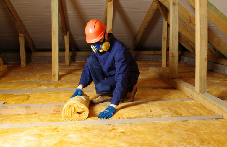
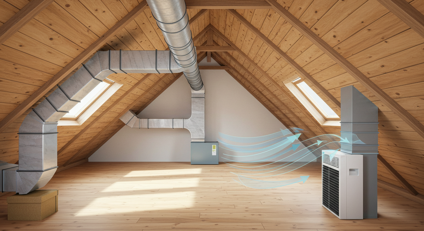
Ducts should ideally exist entirely within the conditioned space. When ducts are run through attics or crawlspaces, they exist “outside” the thermal envelope. In this model, every leak is a 100% loss. By relocating ductwork inside dropped ceilings or between floors, the “leakage” stays within the building’s climate-controlled shell, significantly reducing the energy penalty.
The Static Pressure Reservoir
A duct system is essentially a reservoir of potential energy. The blower motor creates static pressure, which is then converted into velocity at the registers. Leaks act like holes in a dam, bleeding off that potential energy. The goal of a professional sealer is to maintain that “head” of pressure so that air reaches the furthest rooms with enough velocity to ensure proper mixing and comfort.
Classification of Distribution Losses and Sealing Methods
The strategy on how to avoid ductwork leakage varies based on the material and the location of the breach.
| Duct Material | Typical Leak Location | Best Sealing Method | Trade-off |
| Galvanized Steel | Longitudinal seams & elbow gores | Fiber-reinforced mastic | Messy application; long cure time |
| Flexible Ducting | Inner liner at the plenum connection | Zip-ties + UL 181 tape | Prone to installation error |
| Duct Board | Corner joints & tape failure | Glass fabric + mastic | Fragile; high particulate risk if cut |
| Snap-Lock Pipe | Longitudinal seam | Foil tape (UL 181A-P) | Tape can fail if pipe is oily |
Strategic Decision Logic
The decision between manual sealing (mastic) and aerosolized sealing depends on accessibility. If the ductwork is buried behind drywall, manual sealing is impossible without significant demolition. In these cases, aerosol-based sealing—where a polymer fog is pressurized inside the ducts to plug holes from the inside—is the only viable engineering solution, despite its higher cost.
Detailed Real-World Scenarios How to Avoid Ductwork Leakage
Scenario A: The Luxury Attic Retrofit
A homeowner installs a high-SEER variable-speed heat pump in a 1980s home but finds the upstairs rooms remain hot.
-
Diagnosis: The new variable-speed motor runs at lower RPMs for longer periods. Because the ducts in the attic are leaky, the low-velocity air loses all its “coolth” to the 130-degree attic before reaching the registers.
-
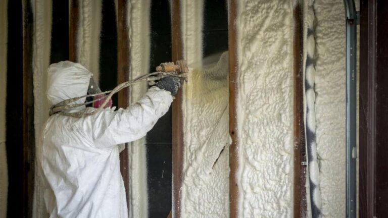
Intervention: Encapsulating the attic with spray foam or sealing all duct joints with mastic and wrapping them in R-8 insulation.
-
Result: The system can finally utilize its high-efficiency stages because the distribution integrity matches the plant’s capability.
Scenario B: Commercial High-Rise Exhaust Failure
A commercial kitchen exhaust system is failing to pull enough air, causing odors to bleed into a dining area.
-
Diagnosis: The vertical riser has developed leaks at the floor penetrations due to building settling.
-
Intervention: Internal aerosol sealing to avoid tearing out the kitchen’s decorative stonework.
-
Failure Mode: If the aerosol is applied without cleaning the grease from the ducts first, the polymer will fail to bond, leading to a secondary failure within months.
Planning, Cost, and Resource Dynamics
The economics of air distribution involve a high upfront labor cost but offer some of the most stable ROIs in building management.
| Resource Scale | Cost Basis | Labor Intensity | Payback Period |
| DIY Manual Sealing | $100 – $300 | Very High | 1–2 Years |
| Professional Mastic Sealing | $1,500 – $3,500 | High | 3–5 Years |
| Aerosolized Internal Sealing | $2,500 – $5,000 | Moderate | 4–7 Years |
Opportunity Cost
The opportunity cost of ignoring duct leaks is the “shortened equipment life” tax. A leaky system forces the compressor and blower to run for 20-30% longer to meet the thermostat’s demand. This accelerates bearing wear and capacitor failure, often leading to a $5,000 replacement five years earlier than necessary.
Technical Strategies and Support Systems
-
Duct Blaster Testing: The gold standard for measuring leakage. It provides a “leakage area” equivalent, telling you if your holes add up to the size of a quarter or a hula hoop.
-
Pressure-Sensitive UL 181A Tapes: Unlike standard tape, these are engineered for the thermal cycles of HVAC systems.
-
Fiber-Reinforced Mastic: A “liquid gasket” that remains flexible when dry, allowing it to withstand the vibration of the system.
-
Static Pressure Manometers: Tools that help technicians ensure that sealing the leaks hasn’t pushed the system’s internal pressure into a dangerous range.
-
Thermal Imaging (FLIR): A non-invasive way to “see” cold air leaking into a hot attic, making it easy to prioritize which sections of ductwork to attack first.
Risk Landscapes and Compounding System Failures
Duct leakage is a “gateway” problem that leads to more severe structural issues.
-
The Humidity Incursion: If return ducts in a damp crawlspace are leaky, they pull in humid air. This moisture condenses on the evaporator coil, leading to “Dirty Sock Syndrome” (bacterial growth) and eventual mold colonization of the supply ducts.
-
The Backdrafting Risk: In a tight house with leaky supply ducts, the resulting negative pressure can pull carbon monoxide from a gas water heater back into the living space.
-
The Particulate Loop: Leaky returns in a dusty attic bypass the main air filter, dumping fiberglass and dust directly into the lungs of the occupants.
Maintenance Governance and Long-Term Adaptation
A strategy on how to avoid ductwork leakage is not a one-time event; it requires a governance protocol.
-
Annual Visual Inspections: Check for “telltale dust.” If there is a dark streak of dust on the outside of a joint, it means air is whistling through and acting as a filter.
-
Post-Trade Audit: If a plumber or electrician has been working in the attic, the ducts must be inspected. Trade professionals often move or step on flexible ductwork, tearing connections or crushing inner liners.
-
The 10-Year Pressure Check: Every decade, a system should be re-tested for leakage. Building settling and thermal cycling inevitably create new gaps.
Measurement, Tracking, and Evaluation
Verification is the difference between “hoping” the ducts are sealed and “knowing” they are.
-
Leading Indicator: Static pressure readings. If static pressure increases after sealing, it proves the “holes” have been closed.
-
Lagging Indicator: Utility bill normalization. Comparing kilowatt-hour usage against “Heating Degree Days” to see if the building is performing more efficiently than the previous year.
-
Documentation Example: A “Duct Integrity Certificate” showing the CFM25 (leakage at 25 Pascals) before and after the intervention.
Common Misconceptions and Oversimplifications
-
Myth: “My ducts are in the ceiling, so leaks don’t matter.”
-
Correction: If the space above the ceiling is unconditioned, the loss is total. Even if it is conditioned, the air isn’t reaching the specific zone where it’s needed, causing temperature imbalances.
-
-
Myth: “Duct tape is for ducts.”
-
Correction: Code specifically prohibits standard cloth-backed duct tape for HVAC sealing because it fails under thermal stress.
-
-
Myth: “New ducts don’t leak.”
-
Correction: Industry studies show that new “code-minimum” installations often have 10-15% leakage unless specifically commissioned for high performance.
-
-
Myth: “Sealing ducts causes mold.”
-
Correction: Only if you seal supply ducts but leave return ducts leaky in a humid crawlspace. A balanced, sealed system actually prevents mold by controlling humidity.
-
Conclusion
The pursuit of how to avoid ductwork leakage is essentially a pursuit of building precision. In an era where energy efficiency is a primary architectural mandate, the tolerance for “invisible” waste is shrinking. By approaching the air distribution network as a pressurized vessel that requires rigorous sealing, mechanical support, and periodic verification, facility managers and homeowners can reclaim a significant portion of their energy budget. The longevity of the HVAC plant and the health of the interior atmosphere depend entirely on the integrity of the vessels that carry the air. It is a fundamental engineering discipline that pays dividends in comfort, safety, and financial performance for the life of the structure.