How to Avoid Electrical System Overload: The Definitive 2026 Engineering Guide
The modern electrical environment is defined by an unprecedented density of demand. In the transition to 2026, our reliance on the domestic and commercial grid has evolved from simple lighting and appliance support to the high-stakes integration of electric vehicle (EV) charging, distributed renewable energy, and the constant thermal load of high-performance computing. How to Avoid Electrical System Overload. This surge in intensity has rendered many legacy distribution systems obsolete, pushing the physical limits of copper and aluminum conductors beyond their engineered safety margins.
Electrical system failure is rarely a spontaneous event; it is a cumulative process of thermal degradation. When the current flowing through a conductor exceeds its rated ampacity, the resulting heat compromises the molecular integrity of the insulation. Understanding the mechanics of overcurrent is no longer a niche requirement for master electricians—it has become a fundamental necessity for facility managers and homeowners managing complex energy ecosystems.
To address the challenge of how to avoid electrical system overload, one must move beyond the superficial advice of “don’t plug in too many devices.” A sophisticated approach requires a rigorous examination of circuit topology, the calculation of diversified loads, and the implementation of proactive monitoring technologies. This article provides a flagship-level editorial analysis of the risks, strategies, and technical frameworks required to maintain a resilient electrical infrastructure in an era of skyrocketing demand.
Understanding “how to avoid electrical system overload”
The strategy of how to avoid electrical system overload is frequently oversimplified as merely preventing a circuit breaker from tripping. In reality, a tripped breaker is a symptom of a protective system functioning as designed. The true goal is to ensure that the demand profile of a building never reaches the threshold where the protection must intervene. This requires an understanding of “Continuous” versus “Non-Continuous” loads. According to most electrical codes, a continuous load—one that runs for three hours or more—must not exceed 80% of the circuit’s rated capacity to prevent heat accumulation.
From a multi-perspective view, the structural engineer sees an electrical system as a thermal source that must be dissipated, while the IT manager sees it as a critical uptime dependency. The risk of oversimplification lies in assuming that all outlets in a room are on different circuits. Often, an entire suite of rooms shares a single 15-amp or 20-amp bus, creating a hidden bottleneck.
Furthermore, the integration of “Smart Home” technology adds a layer of complexity. While these devices allow for granular control, they also possess their own “phantom loads” and can create sudden, synchronized spikes in demand (such as a multi-room climate control system activating simultaneously). A professional-grade plan for avoidance must account for these peak-coincidence factors, using load-shedding logic to prioritize critical systems over secondary conveniences.
Historical Context: From Edison to the Smart Grid
The early electrical grids were designed for a world of predictable, low-density loads—primarily incandescent bulbs and simple motors. The standard 60-amp or 100-amp service entry of the mid-20th century was more than sufficient for a household where the most demanding device was a vacuum cleaner or a toaster. The primary safety concern was the “fuse,” a sacrificial link that would melt under pressure.
The 1970s and 80s brought the proliferation of high-wattage kitchen appliances and central air conditioning, necessitating the jump to 200-amp service and the standardization of magnetic-thermal circuit breakers. By 2026, we have entered the “Digital Power” era. The grid is no longer a one-way street; buildings now act as “prosumers,” generating solar power and feeding it back.
Conceptual Frameworks for Load Management
The 80% Rule (The Safety Margin)
This is the foundational mental model for any electrical plan.
-
Logic: If a circuit is rated for 20 amps, it should only be tasked with a 16-amp constant load.
-
The “Why”: The remaining 4 amps act as a “thermal buffer” to account for start-up surges and environmental temperature fluctuations.
The “Diversified Load” Framework
In a large facility, not every device is on at the same time.
-
The Framework: Engineers use “Demand Factors” to estimate the actual load. For example, in a kitchen, it is assumed that the microwave, oven, and dishwasher will not all reach their peak draw simultaneously 100% of the time.
-
Risk: This framework fails when a specific event (like a holiday dinner) forces a 100% coincidence factor, leading to a systemic trip.
The Water Pipe Analogy (Voltage vs. Amperage)
-
The Framework: Voltage is the pressure; Amperage is the flow rate.
-
Application: An overload is equivalent to trying to force 50 gallons of water per minute through a pipe designed for 10 gallons. The “friction” in the wire is resistance, which manifests as heat.
Key Categories of Overload Prevention and Variations
| Strategy Category | Best Application | Primary Trade-off |
| Sub-Panel Distribution | Large homes / Multi-story | High initial cost; complicates troubleshooting. |
| Dedicated Circuits | High-draw (HVAC, EV, Servers) | Requires invasive wiring; ensures total isolation. |
| Smart Load Shedding | Off-grid / Solar-integrated | Relies on software; can shut off secondary loads. |
| Power Factor Correction | Industrial / Large Motors | Increases efficiency; expensive capacitor banks. |
| Active Monitoring | Data Centers / Luxury Residential | Provides real-time data; adds “phantom” draw. |
Decision Logic for System Upgrades
If a facility is experiencing frequent “nuisance trips,” the logic must first eliminate “Ground Faults” or “Arc Faults.” If the breaker is tripping simply due to volume, the decision to install a sub-panel versus a higher-amperage main breaker depends on the “Point of Use.” If the loads are concentrated in one wing (like a home office or workshop), a sub-panel is the most efficient solution.
Detailed Real-World Deployment Scenarios How to Avoid Electrical System Overload

Scenario 1: The Modern Home Office (Tangerang, Indonesia)
-
Constraint: A 1990s-era home with 1300VA total service being used for high-end video editing and 3D printing.
-
Decision Point: Upgrade the service entry or implement time-of-use management?
-
Outcome: The user implemented a staggered schedule—printing at night and editing by day—while adding a dedicated 20-amp circuit for the server rack to avoid the main service breaker from overheating.
Scenario 3: The Multi-Unit Residential Garage
-
Constraint: Retrofitting an apartment building for 10 EV chargers on a shared 200-amp service.
-
Failure Mode: Without “Dynamic Load Management,” if all ten cars plug in at 6:00 PM, the main building fuse will blow.
-
Solution: An EVSE (Electric Vehicle Supply Equipment) system that communicates, dividing the available amperage equally among the cars so the 200-amp limit is never breached.
Planning, Cost, and Resource Dynamics
The cost of avoiding an overload is significantly lower than the cost of a fire-related rebuild.
| Expenditure Item | Estimated Cost (US) | Lifecycle Value |
| Service Entry Upgrade (200A) | $2,500 – $5,000 | Increases property value and safety. |
| Whole-Home Surge Protection | $300 – $600 | Protects electronics from voltage spikes. |
| Smart Energy Monitor | $150 – $400 | Identifies “vampire” loads and peaks. |
| Professional Audit | $500 – $1,500 | Professional verification of load balance. |
Tools, Strategies, and Technical Support Systems
-
Clamp-on Ammeters: The primary tool for measuring “live” draw on a circuit without disconnecting wires.
-
Infrared Thermography: Used to find “Hot Spots” in a panel that indicate a loose connection or an overloaded bus bar.
-
Load-Balancing Transformers: Ensuring that the “Phase A” and “Phase B” of a 240V system are equally loaded.
-
Automatic Transfer Switches (ATS): Essential for systems with generators to prevent back-feeding.
-
Arc-Fault Circuit Interrupters (AFCI): Specialized breakers that detect the unique “signature” of a spark before it becomes a fire.
-
Smart Plugs with Current Sensing: Providing per-device monitoring for non-permanent loads.
-
Harmonic Filters: Used in environments with many LED drivers and computers to “clean” the power and reduce heat in the neutral wire.
Risk Landscape and Compounding Failure Modes
-
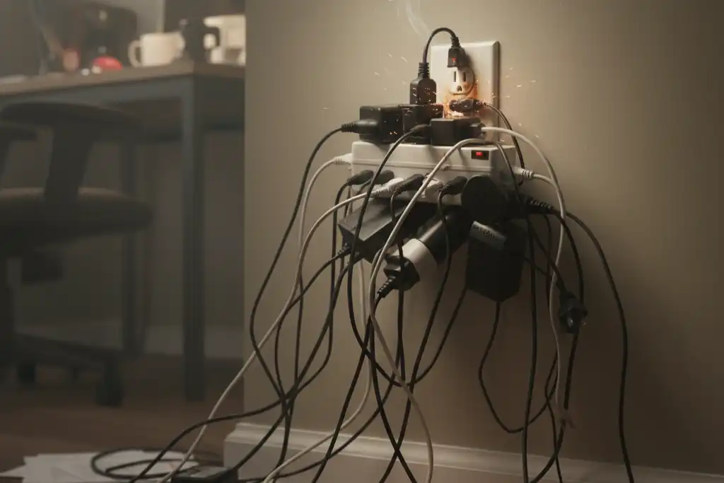
The “Daisy-Chain” Trap: Plugging one power strip into another. This creates a single point of failure that can draw massive amperage through a thin-gauge extension cord.
-
Neutral Wire Overload: In systems with high “Non-Linear Loads” (like computers), the neutral wire can carry current even when the “hot” wires are balanced, leading to overheating in the neutral bus.
-
The “Aged-Breaker” Failure: Over time, the internal springs of a breaker can weaken. A breaker that has tripped 50 times may no longer trip at its rated 20 amps; it might trip at 15, or worse, fail to trip at all (welding shut).
Governance, Maintenance, and Long-Term Adaptation
A resilient system requires “Operational Governance.”
-
Semi-Annual Panel Inspection: Checking for discoloration of wires or the smell of ozone.
-
Tightening Connections: Thermal cycling (expansion/contraction) can loosen screw terminals. A loose wire creates resistance, resistance creates heat, and heat leads to an overload/fire.
-
The “New Device” Protocol: Before adding a high-draw appliance (like an air fryer or portable heater), verify which circuit it will live on and what else shares that wire.
Measurement, Tracking, and Evaluation
-
Leading Indicator: “Average Peak Demand” as reported by a smart meter over a 30-day window.
-
Lagging Indicator: The frequency of breaker trips or the “Heat Signature” of the panel during peak usage.
-
Quantitative Signal: Voltage Drop. If the lights dim significantly when the microwave starts, the circuit is likely undersized for the distance and load, indicating a “Voltage Drop” overload.
Common Misconceptions and Technical Myths
-
Myth: “The breaker will always save me.”
-
Correction: Breakers are mechanical devices that can fail. Furthermore, they don’t protect against “Glowing Connections” (low-current heat).
-
-
Myth: “A power strip adds capacity.”
-
Correction: A power strip adds outlets, not amps.
-
-
Myth: “Higher wattage is always better.”
-
Correction: High-wattage devices are less efficient and increase the risk of overload in older homes.
-
-
Myth: “If the wire is thick, it’s safe.”
-
Correction: A thick wire connected to a thin-gauge internal component (like a cheap outlet) is still a fire risk.
-
-
Myth: “LEDs use no power.”
-
Correction: While efficient, hundreds of LEDs in a commercial space create significant “Inrush Current” when turned on at once.
-
-
Myth: “Extension cords are permanent solutions.”
-
Correction: Cords are for temporary use; they are not rated for the “Continuous Load” of a permanent appliance.
-
Conclusion: The Synthesis of Resilience and Oversight
Learning how to avoid electrical system overload is a transition from reactive emergency management to proactive infrastructure stewardship. In the high-density energy environment of 2026, we must treat our electrical systems as limited resources that require precise allocation. By balancing loads across phases, respecting the 80% rule, and utilizing modern monitoring tools, we can ensure that our transition to an electrified future is both sustainable and safe. The ultimate goal is an invisible grid—one that performs so reliably that the mechanics of demand never interrupt the flow of modern life.